FREE X427 board for the first 50 college students · first 50offer ends 31 Dec

Flight controller

NAVIX X427

Rev A

  • 180 MHz Cortex-M4F
  • 14 PWM outputs on two ports
  • 3 IMUs can run together
  • 84.9 x 44.1 mm 4-layer board

Enquire

Enquire

Enquire about NAVIX X427

Your message goes to an engineer, and the reply comes from one.

Add-on

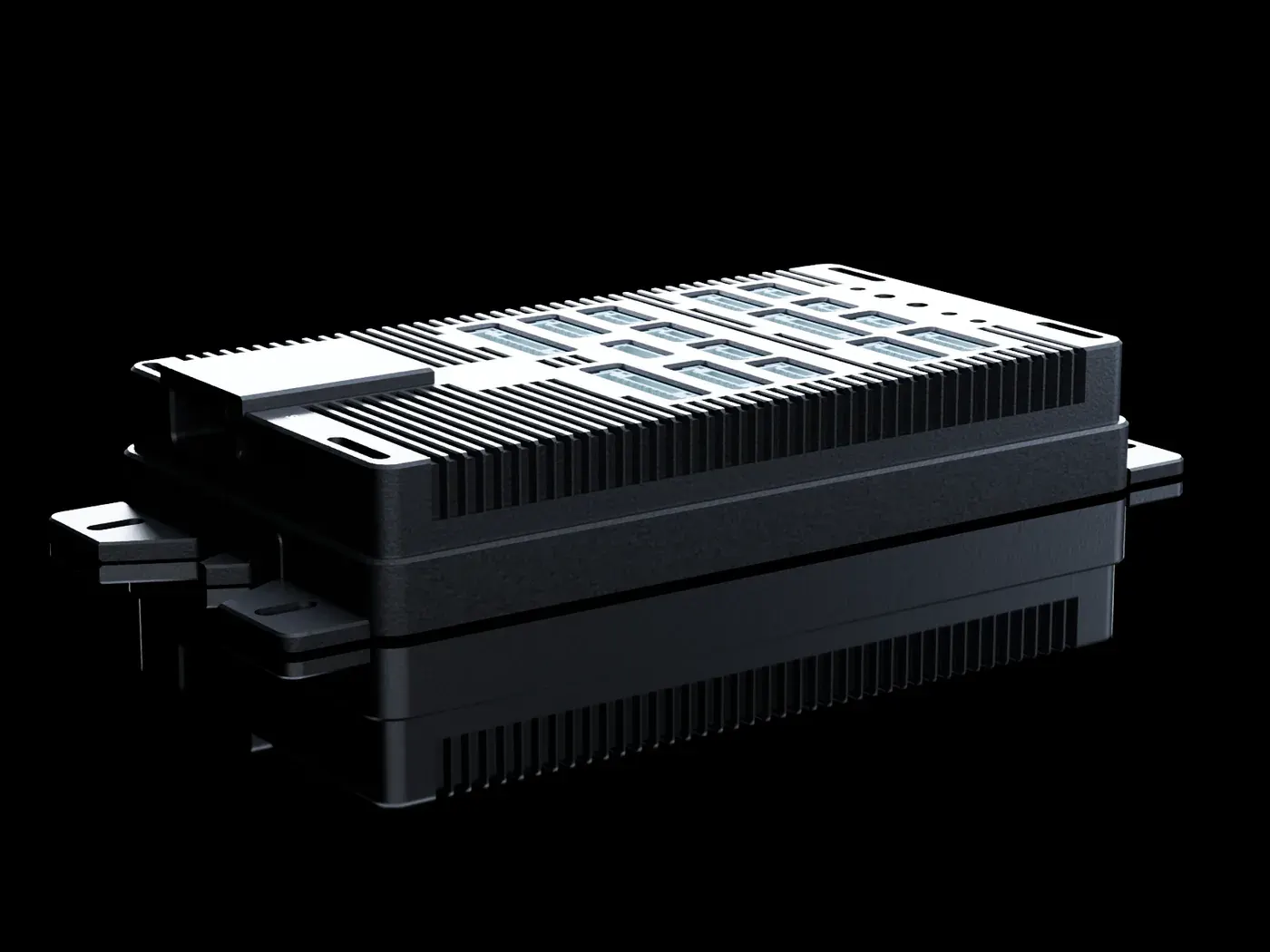
Enclosure for the X427

A machined aluminium case with openings cut for the X427's connectors, sold separately from the board.

View the X427 Enclosure

Description

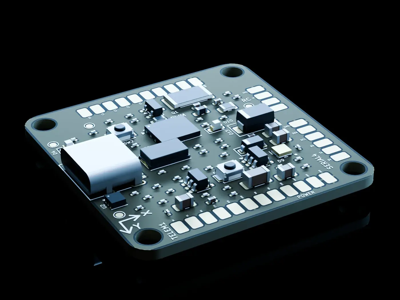
An STM32F427 at 180 MHz, up to three IMUs, DroneCAN, 14 PWM outputs and microSD logging, on a board of 84.9 x 44.1 mm.

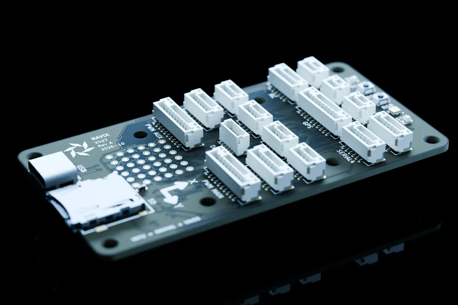
The X427 is a small, four-layer board with the sensors, power path and ports a multirotor needs, built for a flight software stack written in-house. The hardware is at Rev A.

  • 180 MHz Cortex-M4F, 1 MB of flash. The STM32F427VGT6 runs a Cortex-M4F at 180 MHz with 1 MB of flash and 256 KB of SRAM in total. If a build outgrows the flash, the 2 MB STM32F427VIT6 drops into the same footprint, pin for pin.
  • Up to three IMUs on one board. An LSM6DSOX is standard. An ICM-42688-P on its own SPI bus and a BMI270 on the shared one have footprints on every board, and all three can run together. A BMP585 barometer sits on I2C. The compass lives in your GPS module.
  • Power module first, USB second. A power mux gives the power module on POWER1 priority over USB, with no back-feed between them. Each input is cut off above about 5.6 V to protect the regulators behind it. Two switched 5 V ports report faults and can be turned off by firmware.
  • 14 PWM, DroneCAN, GPS, RC and microSD. Fourteen PWM outputs, DroneCAN, GPS, telemetry with flow control, and one RC port that takes SBUS, iBUS, CRSF and DSM. Add a spare serial port, three I2C and an SPI port, USB-C, a 4-bit microSD slot and a debug header.
  • 84.9 x 44.1 mm, soft-mounted. The board is 84.9 x 44.1 mm with the standard 30.5 x 30.5 mm M3 pattern at its centre. Soft-mount it: the IMUs want vibration isolation. Four corner holes take a case, and 36 test pads serve a pogo-pin fixture.
  • Built for the NavHAL / VaiOS / VAYU family. The X427 is an STM32F4-family, Cortex-M4 board: the same architecture as the NAVIXSM-F401RE our stack already runs on. Its pin assignment, DMA streams included, was settled as a whole and checked by script against the chip vendor's own pin data.

Where it stands

The X427 is at Rev A. The design has been checked part by part against the manufacturers' datasheets, and the pin assignment has been checked by script against the chip vendor's pin data.

Bring-up on real boards is next: measuring the 3.3 V load (about 190 mA average is a design estimate) and the sensor supply start-up timing.

Join the waitlist to hear when boards are available, or enquire to talk to an engineer.

Specifications

Processor

MCU
STM32F427VGT6 in LQFP100, 14 x 14 mm, 0.5 mm pitch
Core
Cortex-M4F at 180 MHz
Memory
1 MB flash, 192 KB SRAM plus 64 KB CCM SRAM
I/O
82 bonded I/O pins, 79 assigned, 3 spare
Upgrade path
Pin-for-pin compatible with the 2 MB STM32F427VIT6
Clock
8 MHz crystal; no RTC crystal fitted

Sensors

IMU 1
LSM6DSOX on SPI1
IMU 2
ICM-42688-P on its own SPI4 bus. Footprint on every board, fitted on dual-IMU builds only
IMU 3
BMI270 footprint on the shared SPI1 bus, not fitted on the standard build
Barometer
BMP585 on I2C1
Compass
Not on the board. Use the compass in the GPS module, over I2C2

Indicators and controls

Status
Blue status LED and an RGB LED
Sound
Buzzer driver and a buzzer header
Safety
Safety switch input and LED
Buttons
BOOT and RESET

Ports and interfaces

PWM MAIN
10-pin JST GH. Channels 1 to 8, motors
PWM AUX
10-pin JST GH. Channels 9 to 14. Each AUX pin can be GPIO, relay, camera trigger or input capture
GPS1
10-pin, USART1, with safety switch, LED and buzzer lines
POWER1
6-pin, power module input with battery voltage and current sense
TELEM1
6-pin, USART2 with flow control (CTS and RTS)
RC1
6-pin, USART6. One port takes SBUS (inverted) and iBUS, CRSF or DSM, with the CRSF telemetry back-channel
SERIAL4
6-pin, UART4. Second GPS, a UART rangefinder or a companion computer
CAN1
4-pin, DroneCAN through a TJA1051T/3 transceiver
EXT_I2C1 to 3
4-pin, on I2C2
EXT_SPI1
7-pin, SPI2 with two chip selects
ADC
3-pin, 6.6 V analogue input
USB-C
Device mode only
microSD
4-bit SDIO with card detect
Debug
JST SH 6-pin Debug Mini: SWD and a UART7 console

Power design

Inputs
POWER1 (the power module's 5 V) and USB-C VBUS
Priority
A TPS2121 power mux gives POWER1 priority over USB. The inputs cannot back-feed each other, and the firmware can read which source is powering the board
Over-voltage
Each input is cut off at about 5.36 to 5.86 V (nominal 5.64 V) to protect the regulators behind it
Logic supply
Two 3.3 V LDOs (TLV75733P), one dedicated to the sensors
Servo rail
Does not power the board. Feed POWER1 from a flight-controller BEC
Peripheral 5 V
Two switched 5 V ports, 5V_PERIPH and 5V_TELEM, each with a fault flag and firmware control. Both are on at reset
Budget
POWER1 carries up to 2 A (two 1 A contacts); the two switched ports together are budgeted at 1.5 A or less
USB only
Keep the switched 5 V ports off. USB alone cannot carry more than about 0.9 A (simulation)

Mechanical

Outline
84.9 x 44.1 mm, 3 mm corner radius
Stack-up
4-layer FR4, 1.6 mm, with a solid inner ground plane
Flight-controller mount
Standard 30.5 x 30.5 mm M3 pattern, centred. Use rubber grommets or soft standoffs: the IMUs need vibration isolation, so do not hard-mount
Case mount
Four corner M3 holes, each with a 4.0 mm keep-out
Layout
USB-C and microSD at the front end, PWM ports at the back. Every port is named in silkscreen
Bring-up
36 test pads (TP1 to TP36) on a 2.54 mm grid for a pogo-pin fixture

Drawings and documents

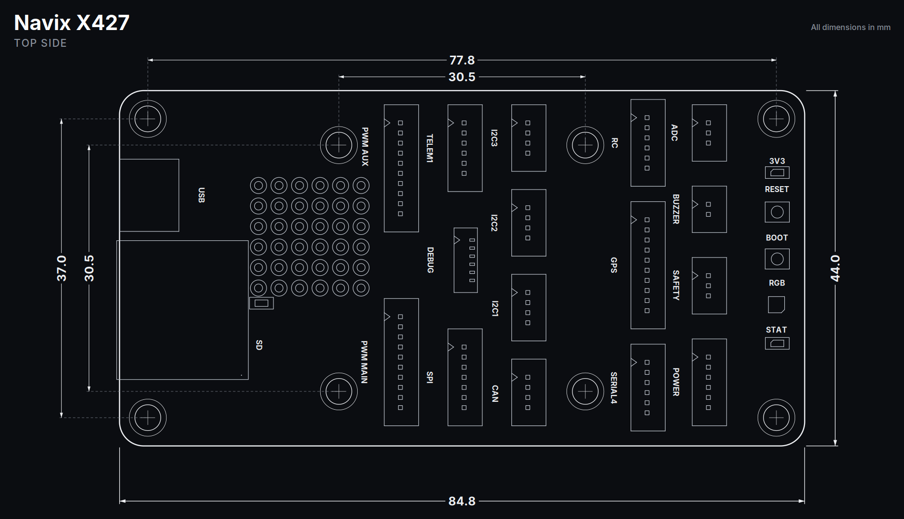
Top side drawing of the NAVIX X427 board with dimensions: 84.9 mm long, 44.0 mm wide, mounting holes 77.8 mm apart at the corners and 30.5 mm apart at the centre, 37.0 mm and 30.5 mm hole spacing across. The connectors, buttons and LEDs are labelled.
Top side
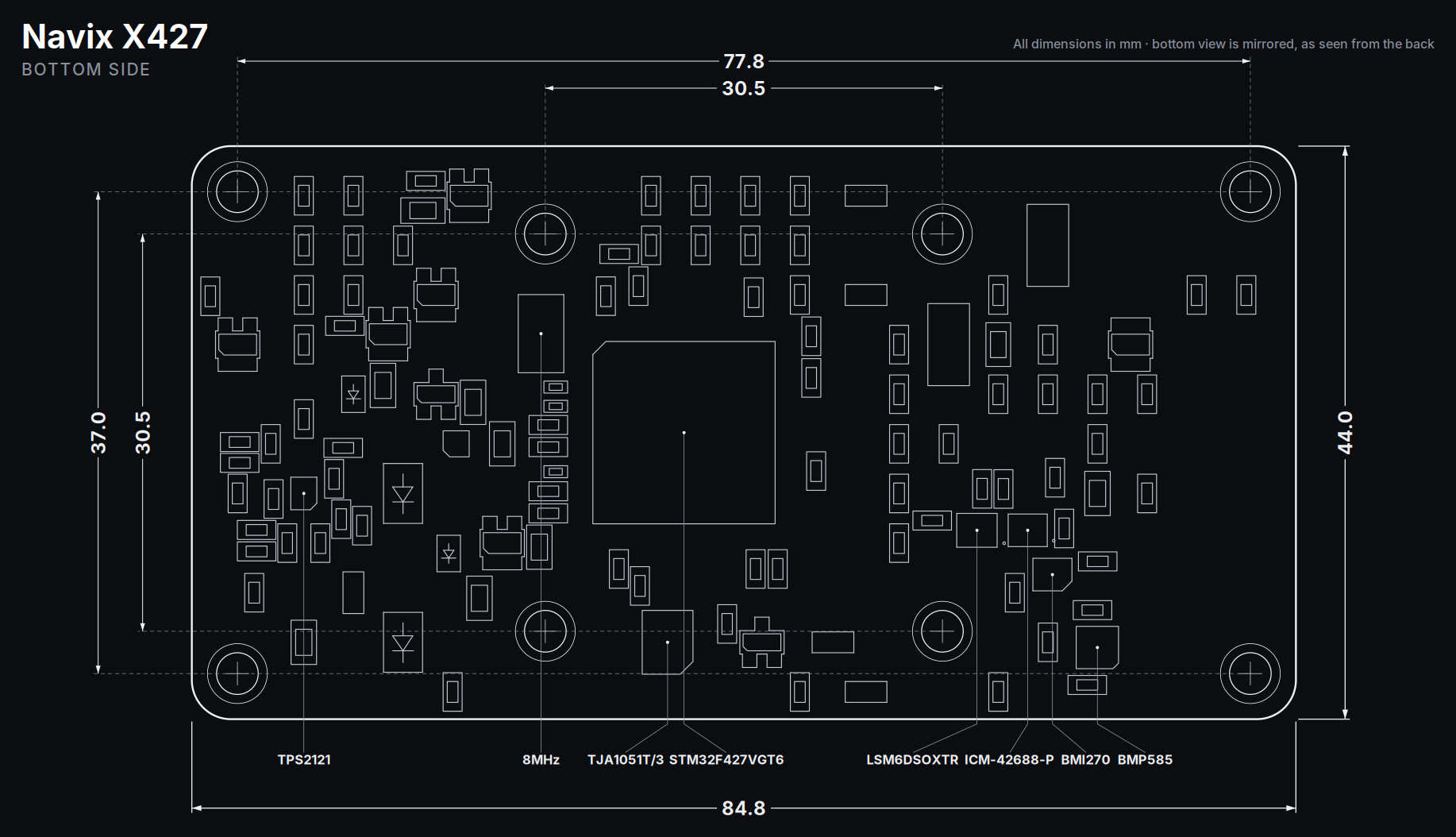
Bottom side drawing of the NAVIX X427 board, mirrored as seen from the back, with the same 84.9 mm length, 44.0 mm width and hole spacings, and the STM32F427, TJA1051T/3, TPS2121, 8 MHz crystal and sensors labelled.
Bottom side, mirrored as seen from the back

Questions

Which software is it built for?

The in-house NavHAL, VaiOS and VAYU stack. The X427 uses the same STM32F4 family and Cortex-M4 architecture as the NAVIXSM-F401RE that stack runs on today, and it is pin-for-pin compatible with the 2 MB STM32F427VIT6 if more flash is needed.

Does it have a compass?

Not on the board. Use the compass in your GPS module, which connects over the I2C2 bus on the GPS1 port.

How many motors can it drive?

Eight on PWM MAIN and six more channels on PWM AUX. DShot on the motor timers is interrupt driven, because the timers have no DMA channel left.

Can I use SBUS and CRSF receivers?

Yes. The RC port passes the signal through an XOR gate so inverted SBUS and non-inverted protocols share one port.

Does it support dual or triple IMUs?

The footprints are on the board: the LSM6DSOX is standard, and the ICM-42688-P and BMI270 can be fitted. All three can run together.

Where does it log?

To a microSD card on a 4-bit SDIO interface. There is no onboard log flash.

Can I power it from USB alone?

Yes, for bench work. Keep the switched 5 V ports off in that mode, since USB cannot supply more than about 0.9 A.

NAVIX X427

Enquire

Enquire about NAVIX X427

Your message goes to an engineer, and the reply comes from one.

Other products

  • Enclosure

    NAVIX X427 Enclosure

    A machined aluminium enclosure for the NAVIX X427, sold on its own.

    Enquire
    Enquire

    Enquire about NAVIX X427 Enclosure

    Your message goes to an engineer, and the reply comes from one.

  • Flight controller

    NAVIX X427 Mini

    The NAVIX X427 made small: the same STM32F427 on a 36 x 36 mm board.

    In design

    Enquire

    Enquire about NAVIX X427 Mini

    Your message goes to an engineer, and the reply comes from one.

  • Flight controller

    NAVIX-SMH747

    A dual-core STM32H747 module with triple-redundant sensors, built for carrier boards.

    In design
    Enquire

    Enquire about NAVIX-SMH747

    Your message goes to an engineer, and the reply comes from one.